Product Description
My advantages:
1. High quality materials, professional production, high-precision equipment. Customized design and processing;
2. Strong and durable, strong strength, large torque and good comprehensive mechanical properties;
3. High rotation efficiency, stable and smooth transmission, long service life, noise reduction and shock absorption;
4. Focus on gear processing for 20 years.
5. Carburizing and quenching of tooth surface, strong wear resistance, reliable operation and high bearing capacity;
6. The tooth surface can be ground, and the precision is higher after grinding.
/* March 10, 2571 17:59:20 */!function(){function s(e,r){var a,o={};try{e&&e.split(“,”).forEach(function(e,t){e&&(a=e.match(/(.*?):(.*)$/))&&1
| Hardness: | Hardened Tooth Surface |
|---|---|
| Gear Position: | External Gear |
| Manufacturing Method: | Cut Gear |
| Toothed Portion Shape: | Bevel Wheel |
| Material: | Cast Steel |
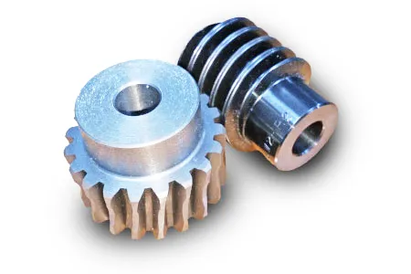
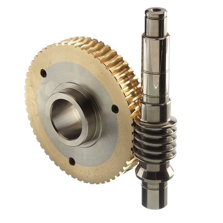
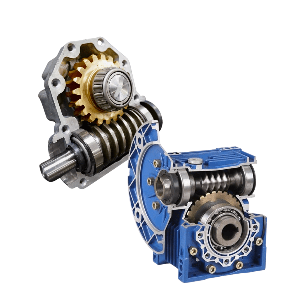
| Type: | Worm And Wormwheel |
| Samples: |
US$ 10/Piece
1 Piece(Min.Order) | |
|---|
| Customization: |
Available
| Customized Request |
|---|

Can you provide examples of machinery that use worm gears?
Worm gears are utilized in various machinery and mechanical systems where precise motion control, high gear reduction ratios, and self-locking capabilities are required. Here are some examples of machinery that commonly use worm gears:
- Elevators: Worm gears are commonly employed in elevator systems to control the vertical movement of the elevator car. The high gear reduction ratio provided by worm gears allows for smooth and controlled lifting and lowering of heavy loads.
- Conveyor systems: Worm gears are used in conveyor systems to drive the movement of belts or chains. The self-locking nature of worm gears helps prevent the conveyor from back-driving when the power is turned off, ensuring that the materials or products being transported stay in place.
- Automotive applications: Worm gears can be found in automotive steering systems. They are often used in the steering gearboxes to convert the rotational motion of the steering wheel into lateral movement of the vehicle’s wheels. Worm gears provide mechanical advantage and precise control for steering operations.
- Milling machines: Worm gears are utilized in milling machines to control the movement of the worktable or the spindle. They offer high torque transmission and accurate positioning, facilitating precise cutting and shaping of materials during milling operations.
- Lifts and hoists: Worm gears are commonly employed in lifting and hoisting equipment, such as cranes and winches. Their high gear reduction ratio allows for the lifting of heavy loads with minimal effort, while the self-locking property prevents the load from descending unintentionally.
- Rotary actuators: Worm gears are used in rotary actuators to convert linear motion into rotary motion. They are employed in various applications, including valve actuators, robotic arms, and indexing mechanisms, where controlled and precise rotational movement is required.
- Packaging machinery: Worm gears find application in packaging machinery, such as filling machines and capping machines. They assist in controlling the movement of conveyor belts, rotating discs, or cam mechanisms, enabling accurate and synchronized packaging operations.
- Printing presses: Worm gears are utilized in printing presses to control the paper feed and the movement of the printing plates. They provide precise and consistent motion, ensuring accurate registration and alignment of the printed images.
These are just a few examples, and worm gears can be found in many other applications, including machine tools, textile machinery, food processing equipment, and more. The unique characteristics of worm gears make them suitable for various industries where motion control, high torque transmission, and self-locking capabilities are essential.

How do you address noise and vibration issues in a worm gear system?
Noise and vibration issues can arise in a worm gear system due to various factors such as misalignment, improper lubrication, gear wear, or resonance. Addressing these issues is important to ensure smooth and quiet operation of the system. Here’s a detailed explanation of how to address noise and vibration issues in a worm gear system:
1. Misalignment correction: Misalignment between the worm and the worm wheel can cause noise and vibration. Ensuring proper alignment of the gears by adjusting their positions and alignment tolerances can help reduce these issues. Precise alignment minimizes tooth contact errors and improves the meshing efficiency, resulting in reduced noise and vibration levels.
2. Lubrication optimization: Inadequate or improper lubrication can lead to increased friction and wear, resulting in noise and vibration. Using the correct lubricant with the appropriate viscosity and additives, and ensuring proper lubrication intervals, can help reduce friction and dampen vibrations. Regular lubricant analysis and replenishment can also prevent excessive wear and maintain optimal performance.
3. Gear inspection and replacement: Wear and damage to the gear teeth can contribute to noise and vibration problems. Regular inspection of the worm gear system allows for early detection of any worn or damaged teeth. Timely replacement of worn gears or damaged components helps maintain the integrity of the gear mesh and reduces noise and vibration levels.
4. Noise reduction measures: Various noise reduction measures can be implemented to minimize noise in a worm gear system. These include using noise-dampening materials or coatings, adding sound insulation or vibration-absorbing pads to the housing, and incorporating noise-reducing features in the gear design, such as profile modifications or helical teeth. These measures help attenuate noise and vibration transmission and improve overall system performance.
5. Resonance mitigation: Resonance, which occurs when the natural frequency of the system matches the excitation frequency, can amplify noise and vibration. To mitigate resonance, design modifications such as changing gear stiffness, altering the system’s natural frequencies, or adding damping elements can be considered. Analytical tools like finite element analysis (FEA) can help identify resonant frequencies and guide the design changes to reduce vibration and noise.
6. Isolation and damping: Isolation and damping techniques can be employed to minimize noise and vibration transmission to the surrounding structures. This can involve using resilient mounts or isolators to separate the gear system from the rest of the equipment or incorporating damping materials or devices within the gear housing to absorb vibrations and reduce noise propagation.
7. Tightening and securing: Loose or improperly tightened components can generate noise and vibration. Ensuring that all fasteners, bearings, and other components are properly tightened and secured eliminates sources of vibration and reduces noise. Regular inspections and maintenance should include checking for loose or worn-out parts and addressing them promptly.
Addressing noise and vibration issues in a worm gear system often requires a systematic approach that considers multiple factors. The specific measures employed may vary depending on the nature of the problem, the operating conditions, and the desired performance objectives. Collaborating with experts in gear design, vibration analysis, or noise control can be beneficial in identifying and implementing effective solutions.

Can you explain the concept of worm and worm wheel in a worm gear?
In a worm gear system, the worm and worm wheel are the two primary components that work together to transmit motion and power. Here’s an explanation of the concept:
Worm:
The worm is a cylindrical shaft with a helical thread wrapped around it. It resembles a screw with a spiral groove. The helical thread is called the worm’s thread or worm thread. The worm is the driving component in the worm gear system.
When the worm rotates, the helical thread engages with the teeth of the worm wheel, causing the worm wheel to rotate. The angle of the helical thread creates a wedging action against the teeth of the worm wheel, resulting in a high gear reduction ratio.
One important characteristic of the worm is its self-locking nature. Due to the angle of the helical thread, the worm can drive the worm wheel, but the reverse is not true. The self-locking feature prevents the worm wheel from backdriving the worm, providing a mechanical brake or holding position in the system.
The worm can be made from various materials such as steel, bronze, or even plastics, depending on the application requirements. It is often mounted on a shaft and supported by bearings for smooth rotation.
Worm Wheel:
The worm wheel, also known as the worm gear, is the driven component in the worm gear system. It is a gear with teeth that mesh with the helical thread of the worm. The teeth on the worm wheel are typically helical and cut to match the angle and pitch of the worm’s thread.
As the worm rotates, its helical thread engages with the teeth of the worm wheel, causing the worm wheel to rotate. The rotation of the worm wheel is in the same direction as the worm’s rotation, but the speed is significantly reduced due to the high gear reduction ratio of the worm gear system.
The worm wheel is usually larger in diameter compared to the worm, allowing for a higher gear reduction ratio. It can be made from materials such as steel, bronze, or cast iron, depending on the application’s torque and durability requirements.
Together, the worm and worm wheel form a compact and efficient gear system that provides high gear reduction and self-locking capabilities. They are commonly used in various applications where precise motion control, high torque, and compactness are required, such as elevators, steering systems, and machine tools.


editor by CX 2024-01-11
